Usual disclaimer about being careful fixing mains powered devices - electricity can kill if you do something stupid!
There's plenty of information about this unit available on the internet, which made troubleshooting and repairing this subwoofer very simple. I'm particularly indebted to Andy Doswell who previously went through the same repair here
The symptoms on my SFX 5.1 were similar to what Andy experienced - my TV viewing was punctuated by a slightly dramatic "thunder" like noise which made me think the neighbours were putting their bins out! Shortly afterwards the power died completely and the sub was unresponsive.
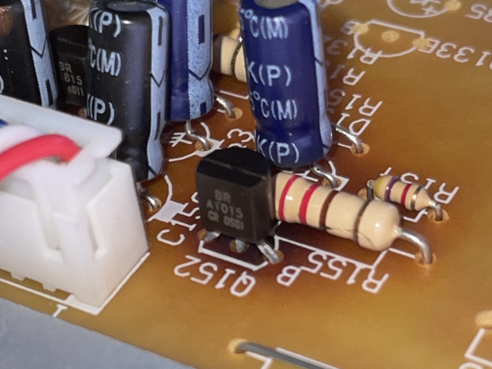
The design of the power board features two transistors used as the +12v and -12v rails, which are pushing the limits of their current draw capabilities and in turn scorching the board. Replacing these transistors with beefier components allows the subwoofer to enjoy a longer and happier life throbbing the bass for your favourite songs or films!
How to open the Tannoy SFX 5.1 Subwoofer
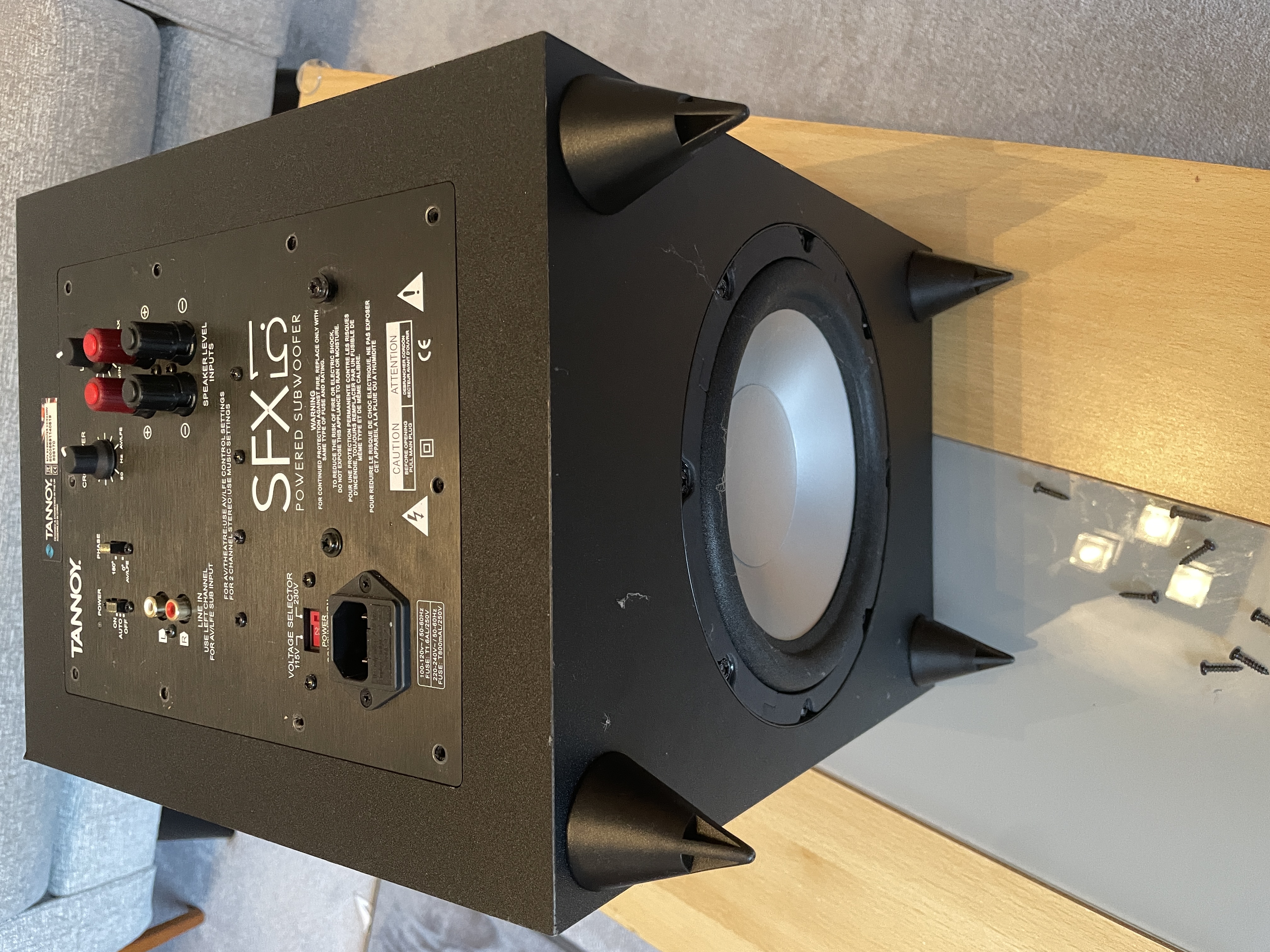
Everything is well-sealed to prevent resonant vibrations due to the powerful low frequencies. This makes it a little more tricky to get to the boards. The boards and power sections themselves are attached to the plate on the back. Removing the 10 screws round the edge of this plate will free the whole lot to come out as one piece but I found it useful to remove the speaker driver and then use my hand through the speaker hole to push the board out from the inside. This avoided cosmetic damage to the edge of the board through trying to prise it out.
Identifying the failed components

The power board is the one at a 90 degree angle, look for Q151 and Q152 and chances are you'll also see the scorch marks where these transistors have endured a hard life running hot. If you're lucky, it'll just be a case of replacing these transistors but bear in mind the heat generated may also have shortened the life of the nearby electrolytic capacitors too, so it might be worth replacing these whilst the board is out.
Beefing up the regulation

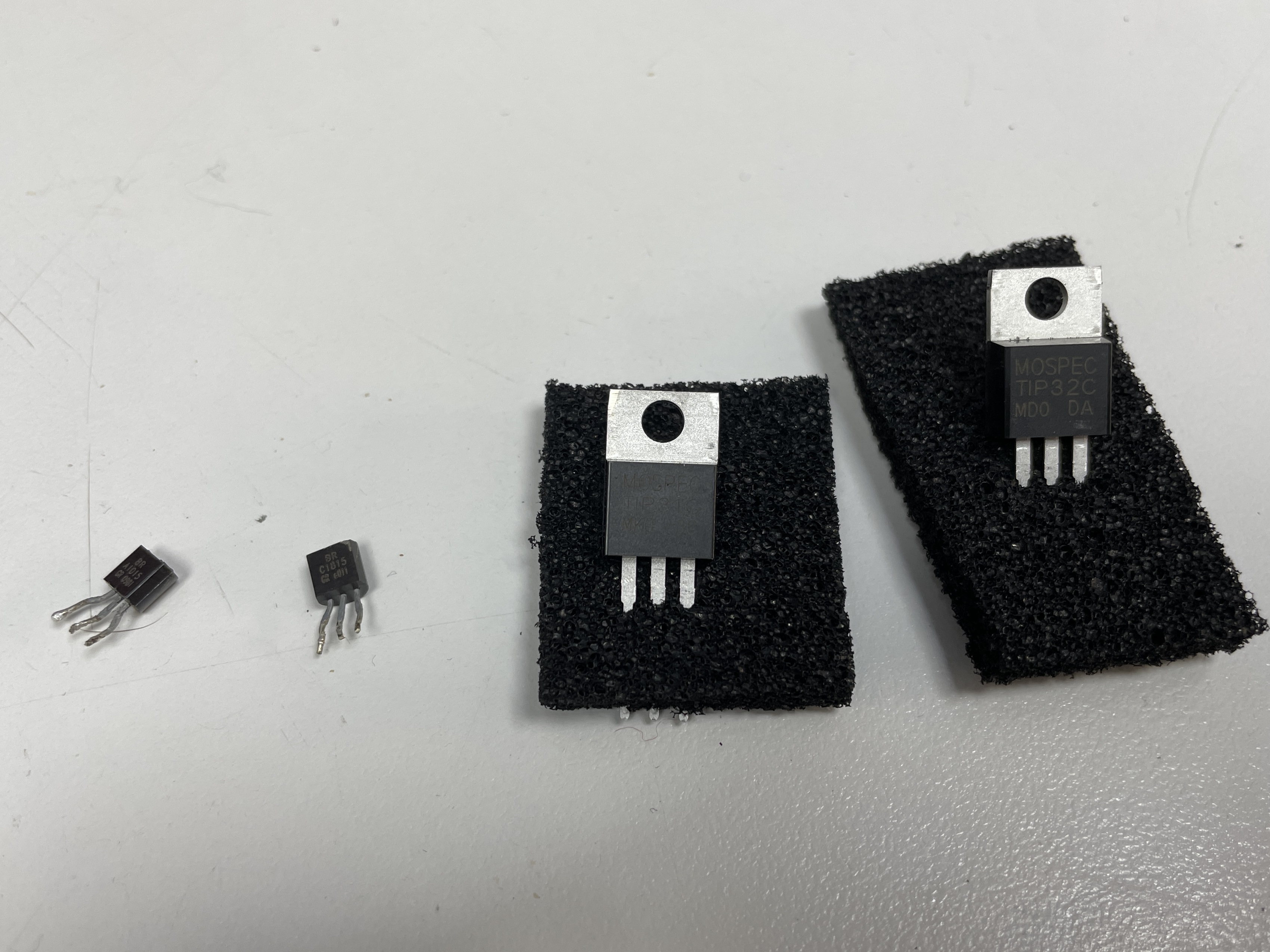
In this picture you can see the original transistors on the left, and the replacements on the right - for Q151 I'm replacing it with a TIP31C and Q152 is being replaced with a TIP32C.
Be careful soldering these onto the board as the solder pads lift very easily - they have had a hard life dissipating all that transistor heat and on my board at least two of them decided to come away without much persuasion. I ended up using solder bridges to remake the connections and buzzing them out with a multimeter to ensure continuity.
The Bass Is Pumping
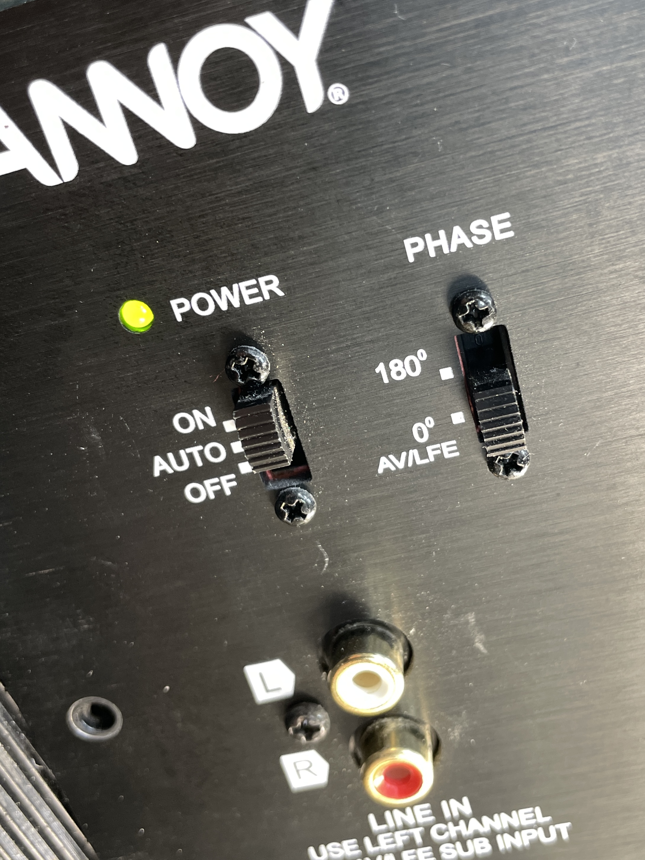
Once you've made the changes pop the boards back into the sub box and reattach the speaker. Power the unit up and all being well you should have your green light on the board. Test with some banging tunes, explaining to the neighbours it's all part of a science experiment!

Did this page help you?
There's no obligation, I've provided this article for free.
But if you saved time, money or frustration as a result of this article, or you just enjoyed reading it, perhaps you might like to